|
|
| Home Product Info Typical Layouts & Details |
|
| Typical Layouts & Details |
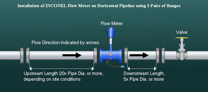
Flow Meter Installation on Horizontal Pipeline using "3 PAIRS OF FLANGES"
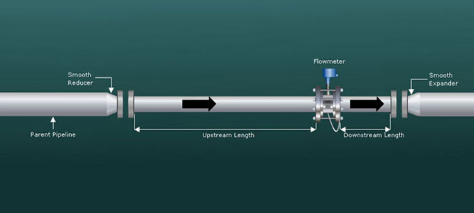
Flow Meter Installation on Reduced Pipeline:
If the parent pipeline is larger than the flow meter size, then the metering pipeline has to be modified to the meter size for short length as depicted in the figure. Please note that reduction & expansion should be smooth.
Flow Meter Installation in Bypass line:
The flow meter is installed in Bypass line as shown in the figure:
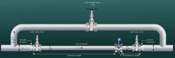
P = Parent Line Size
D = Meter Size Pipe Line
Note:
- On upstream side, we recommend installing Gate valve / Ball valve which should be kept fully open.
- NEVER use Butterfly Valve on upstream side.
- On downstream side any type of valve can be used for controlling the flow.
Flow Meter Installation after 'T' Branch pipeline:
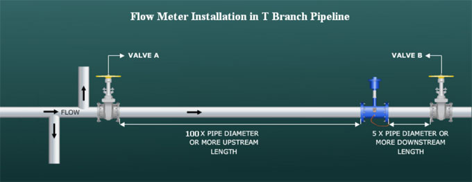
- In the above case flow may be controlled by upstream Valve A, provided the upstream length is at least 100D.
- For complete shutdown of flow through flow meter use Valve A.
- Fine control of flow can be achieved by Valve B.
Flow Meter Installation in Horizontal pipeline with short pipe length Open Discharge:

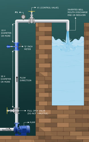
- For Installations as shown above follow correct Upstream & Downstream piping guidelines.
- Use correct size pipe I.D. same as meter I.D.
- Upstream side valve (V1) must always be kept fully open.
- For controlling the flow, only downstream side valve (V2) must be used.
- However, valve V2 must not be kept completely open. Since the downstream pipe length is very short, it is necessary to close valve V2 slightly for creating back pressure in the system.
Flow Meter Installation in Vertical pipeline with short pipe length Open Discharge:
Installation of Insertion Hot Tap Flow Meter:
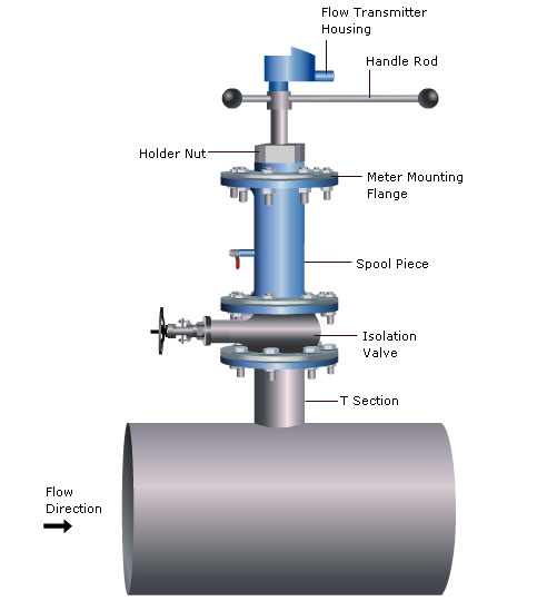
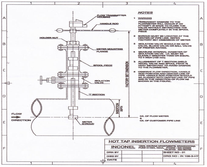
Installation Procedure for INCONEL VFM:
- Refer Table for Upstream / Downstream Piping Length requirement.
- Refer drawing number 150-40-11 for details of flange dimensions and bolt sizes.
- Weld the flanges on both sides of the upstream & downstream side of pipe.
- Position the flow meter so that arrow on the meter body / name plate points in the direction of flow.
- Check alignment and spacing of piping on both sides of meter body location.
- Place gaskets on faces of meter body and position meter body between the flange faces of piping. It is imperative that the gaskets do not protrude into the piping. Gasket I.D.[Inner Diameter] must be at least 5 mm larger than I.D. of pipe and meter. Care should be taken not to use excessively thick gaskets (recommend 3 mm Gasket). DO NOT USE RUBBER GASKETS.
- Insert proper sized bolts through the flanges and run nut on the bolts. Attach a Ground Strap to one of the bolts.
- Partially tighten bolts to hold assembly in alignment. The correct diameter bolts must be used.
- Check alignment of piping and concentricity of gaskets. Bolts should bear against outside of flange holes.
- Tighten nuts evenly as per specified torque.
For flanges of over 150lbs. rating:
- Place the two centering rings on the ends of the meter body.
- The centering rings are left in place after tightening the meter body between flanges.
Note:
- For installations on vertical pipelines carrying liquids, flow direction should be from bottom to top.
- For gases, flow may be in any direction.
|
| |
|
